Every article in this series so far started from the same unspoken assumption — that bits can travel from one end to the other.
There are no bits on the wire. There is a voltage that changes over time, or light that is brighter and dimmer, or a radio wave whose phase shifts. None of those things are zeroes and ones. They are physical quantities measured with decimal points, and they never arrive exactly as the sender intended.
This page is about the work required to make that assumption true.
There are no bits on the wire
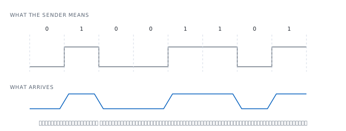
The top trace is what the sender means. Square edges, steady levels, time divided into equal cells, one bit each.
The bottom trace is what arrives. The edges slope because the cable eats high frequencies harder than low ones. The amplitude is lower because the cable has resistance. The shape is distorted because different frequencies travel at different speeds.
The receiver never sees the top trace. It has only the bottom one, and must decide from it what the top one was. Everything on this page is machinery for making that decision correct almost all of the time.
If you have never looked, start here
The machine reading this page will tell you which languages its port speaks.
$ ifconfig -m en5
    supported media:
        media none
        media autoselect
        media 10baseT/UTP mediaopt full-duplex
        media 100baseTX mediaopt full-duplex
        media 1000baseT mediaopt full-duplex
        media 2500Base-T mediaopt full-duplex
        media 5000Base-T mediaopt full-duplex
That list is not just speeds. Every line names a different standard, and inside each one is a completely different encoding scheme — on the same connector, over the same cable.
Notice too that there is no half-duplex option at all. This device no longer supports it, which is a good thing, and the duplex mismatch section explains why.
Problem one — the receiver has no clock
This is the largest problem at this layer, and the one most people do not know exists.
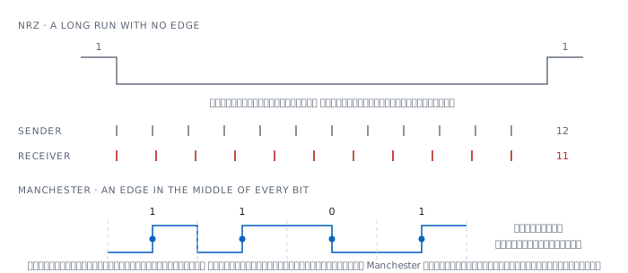
There is no clock wire in the cable. The receiver has to work out for itself where each bit begins. Send it the straightforward way — high for one, low for zero, which is called NRZ — and if the data happens to contain a long run of zeroes, the signal goes flat with no edge to grab.
Two clocks are never exactly equal. A tiny difference is enough. With no edge arriving to reset the timing, the error accumulates until the receiver counts one bit too few, and once it does, everything after that is wrong.
The fix is to make the data force edges to happen, which means sending something that is not data along with it. That is where encoding overhead comes from.
Manchester — paying full price
10BASE-T solves it the bluntest way possible: every bit must have an edge in the middle. A rising edge means one thing, a falling edge the other.
It is a hundred percent guarantee that the line never goes flat, and it costs a hundred percent.
10 Mbit/s of data -> 20 million transitions per secondSo a cable carrying 10BASE-T must handle roughly 20 MHz, for 10 Mbit/s of actual data.
4B/5B — paying a quarter
100BASE-TX refuses to pay that. It uses a cleverer method: take four bits of data and send them as a five-bit code, choosing only those five-bit codes that are guaranteed not to contain a long run of zeroes.
  4 data bits -> 5 bits on the wire
  100 Mbit/s x 5/4 = 125 Mbaud
And that is still not enough, because 125 Mbaud is too high for Cat 5. So another layer called MLT-3 uses three voltage levels instead of two, which divides the fundamental frequency by four.
125 Mbaud / 4 = 31.25 MHzThat 31.25 MHz is what lets Cat 5 carry 100 Mbit/s. Without MLT-3 it would need far better cable.
8B/10B and 64B/66B — the price falls thirty-two times
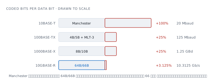
1000BASE-X, gigabit over fibre, uses 8B/10B — eight bits become ten. The overhead is still 25%, so it has to transmit at 1.25 GBd to deliver 1 Gbit/s.
At ten gigabit, 25% is too expensive to accept. 10GBASE-R changes the idea: instead of guaranteeing every bit, guarantee only that there is at least one edge per 66 bits, by adding a 2-bit header and scrambling the rest with a pseudo-random generator so no long pattern survives.
  Manchester    1 bit  -> 2 bits     +100%
  4B/5B         4 bits -> 5 bits      +25%
  8B/10B        8 bits -> 10 bits     +25%
  64B/66B      64 bits -> 66 bits   +3.125%
10 Gbit/s x 66/64 = 10.3125 Gbit/s on the wireThe first line and the last differ by a factor of thirty-two, and the difference is between a flat-rate guarantee and a statistical one — a lesson that travels well beyond network cable.
The same cable, used in completely different ways
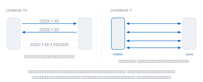
A UTP cable has four pairs. 100BASE-TX uses only two — one to send, one to receive. The other two are not used at all.
1000BASE-T uses all four, and uses them in an entirely different way: every pair sends and receives simultaneously.
  1000 Mbit/s / 4 pairs         =  250 Mbit/s per pair
  PAM-5 carries 2 bits/symbol   -> 125 Mbaud per pair
125 Mbaud is exactly the same number as 100BASE-TX. That is why the Cat 5 already in the walls could carry gigabit although it was never designed to. Gigabit did not push the frequency up. It spread the same frequency across four pairs and packed more data into each symbol.
Sending both ways on one pair creates two new problems.
First, the receiver hears itself. Its own transmission reflects back and mixes with the far end's signal, so it must subtract its own echo before it can read anything.
Second, somebody has to supply the clock. When both ends talk at once over the same medium, they cannot each use their own clock. 1000BASE-T therefore has to agree which side is master and supplies timing, and which is slave and follows. That agreement can fail, and there is a status bit reserved for saying so.
Problem two — the cable is an analogue thing
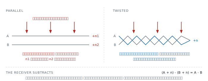
Why the pairs are twisted
The short answer is that the receiver does not measure voltage against ground. It measures the difference between two wires.
If external noise reaches both wires equally, it disappears in the subtraction.
(A + n) - (B + n) = A - BThe whole condition lives in the word equally. Two wires laid side by side are not equally far from a noise source; the nearer one picks up more.
Twisting makes the two wires swap positions continuously along the run, so their average distance from any noise source is the same. The noise they pick up is then equal, and really does cancel.
This is why untwisting a long tail when terminating a plug is a real defect and not a matter of neatness.
Loss depends on frequency, not only on length
Copper always eats high frequencies harder than low ones. The measurement is in decibels and is called insertion loss.
TIA-568.2-D sets a maximum at every frequency for every cable category. A concrete example: a Cat 6A channel at 500 MHz may lose no more than 39.1 dB.
That number explains a symptom many people have met — a cable that is too long or too poor does not lose everything, it loses the high frequencies, which means it still works at low speed and fails when you speed it up.
Crosstalk — the neighbours inside the same jacket
Four pairs share one jacket, so each pair is a noise source for the others. That is crosstalk, and it is measured both at the transmitting end and at the far end.
Twisting helps here too, and it is why each pair in a cable is twisted at a different pitch. If they all had the same pitch, two adjacent pairs would hold the same relative position for the whole run, and the cancellation would fail.
By the time you reach 1000BASE-T, where every pair carries both directions at once, crosstalk rather than loss becomes the limiting factor. That is why a cable certified for 100 Mbit/s may fail certification for gigabit at exactly the same length.
Why it stops at one hundred metres
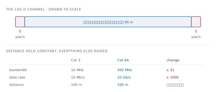
A hundred metres is not the distance a signal can no longer travel. It is a budget fixed at the start, with everything since designed to fit inside it.
The 802.3 channel model divides it explicitly.
  90 m   solid-core cable run in the wall
  10 m   stranded patch cord, 5 m at each end
  ----
  100 m
The two cable types are not the same. Patch cord uses stranded conductors so it can flex, which costs more loss per metre. That is why the 10 metres is budgeted separately.
What is more interesting is what did not change. From Cat 3, characterised to 16 MHz for 10 Mbit/s, through to Cat 6A, characterised to 500 MHz for 10 Gbit/s.
  cable bandwidth    16 MHz  -> 500 MHz    x 31
  data rate          10 Mb/s -> 10 Gb/s    x 1000
  distance          100 m    -> 100 m      unchanged
The gap between 31 times and 1000 times is the work of encoding alone. The cable got thirty times better and carries a thousand times more; the remaining factor of thirty came from using more pairs, more voltage levels, and thriftier codes.
Freezing the distance was a very good design decision, because it means cable buried in a wall twenty years ago still has a chance of meeting a new standard. Had distance been allowed to shrink with speed, every upgrade would mean opening walls.
Problem three — both ends must agree what to speak
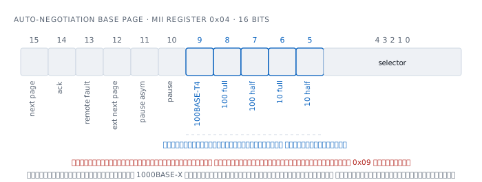
A port speaks several languages, as the supported media list above shows. How do two ends agree, when they cannot yet talk to each other?
The answer is auto-negotiation, built on top of something that already existed — 10BASE-T sends short pulses periodically to say it is alive. Auto-negotiation turns that single pulse into a burst of pulses carrying data. Older equipment that does not understand it still sees a pulse saying somebody is alive, so backward compatibility came free.
And the structure of that burst explains why the base page is exactly 16 bits wide.
  33   pulse positions per burst
  17   odd positions, carrying clock
  16   even positions, carrying data
That 16 is the whole base page. The register's size does not come from software convenience; it comes from how many pulses fit in one burst, and a burst is repeated every 16 milliseconds, plus or minus 8.
What is in the base page
What gets exchanged is a 16-bit register, checkable in real source at include/uapi/linux/mii.h in the Linux kernel.
  bit   name           meaning
  15    NPAGE          more pages follow
  14    LPACK          acknowledging what the far end sent
  13    RFAULT         this end is reporting a fault
  12    XNP            extended next page
  11    PAUSE_ASYM     asymmetric flow control
  10    PAUSE_CAP      flow control
   9    100BASE-T4     a standard that died
   8    100FULL
   7    100HALF
   6    10FULL
   5    10HALF
  4-0   SLCT           says this is the 802.3 family
Everything a port can advertise fits in five bits, 9 down to 5, and one of those five is a standard that no longer exists.
There is no gigabit bit here at all, because gigabit did not exist when this was designed. It was added later in a separate register, 0x09, which in the same source is
  ADVERTISE_1000FULL   0x0200   in register 0x09
  ADVERTISE_1000HALF   0x0100   in register 0x09
This is a design seam visible directly in the code. A field intended to be extensible was actually extended, and it works — but a single port's abilities now live across several registers ordered by when the standards shipped rather than by any logic.
The same bit position, a different meaning
What makes people reading the code stop is a set of lines like these, in one file.
  ADVERTISE_10HALF      0x0020
  ADVERTISE_1000XFULL   0x0020

  ADVERTISE_10FULL      0x0040
  ADVERTISE_1000XHALF   0x0040
This is not a mistake. The same bit position means different things depending on whether the port is copper or 1000BASE-X fibre, because the two use different negotiation schemes over the same register.
The practical consequence is that reading a raw register value without knowing the port type gives an answer that looks reasonable and is entirely wrong.
Duplex mismatch — the quietest failure here
Auto-negotiation can fail in the worst possible way: fail, and bring the link up anyway.
If one end is hard-set to 100 full, that end stops sending negotiation bursts altogether. The other end, still trying to negotiate, hears nothing at all.
The standard has a fallback for this, called parallel detection: look at the signal itself and work out what the far end is speaking. That gives you the speed, because 10BASE-T and 100BASE-TX look clearly different on the wire.
But it cannot give you the duplex, because the signal carries no such information. Unable to know, it must take the safer side, which is half duplex.
So one end is full and the other is half, on the same cable.
- The full end transmits whenever it likes, without listening first
- The half end listens before transmitting, and aborts a frame if it detects a collision partway through
The half end therefore sees late collisions, while the full end sees the aborted frames as damaged and counts them as CRC errors.
And the link stays up. It works, it pings, it is merely very slow under load — a symptom people almost always blame on something else first.
Problem four — signals take time to travel
An electrical signal in copper does not travel at the speed of light in a vacuum. The ratio is called NVP, runs about 0.6 to 0.9, and test equipment usually defaults to 0.7 for twisted pair and 0.82 for coax.
At around 67% of light speed, the number worth memorising is roughly 20 centimetres per nanosecond.
  light in vacuum        30 cm/ns
  copper at NVP 0.67     20 cm/ns
  1 m                     5 ns
  100 m                 500 ns   one way
This matters in two real ways.
First, it is how cable length is measured. A tester launches a pulse and times the reflection from a break or a bad joint, then converts time into distance using NVP. The technique is called TDR, and it appears in the worked examples below.
Second, it is where the 64-byte minimum frame comes from. In the Ethernet article, the reason a frame must be long enough is that the sender has to still be transmitting when news of a collision gets back to it — a calculation made purely out of travel time.
Problem five — at high speed, errors become certain
At low speed a wrong bit is a rare event. Detect it with the FCS, discard the frame, let a higher layer send it again. That is enough.
At sufficiently high speed it stops being enough, because there are so many bits per second that wrong bits happen constantly. Discard the whole frame every time and nothing gets through at all.
The fix is to change from detecting to correcting — send enough redundancy that the receiver can repair wrong bits itself without asking again. That is FEC.
IEEE 802.3 working group material names the codes used: the 802.3bj work refers to a Reed-Solomon code, RS(528, 514), together with 256B/257B transcoding, while 802.3bz, which produced 2.5G and 5GBASE-T, uses LDPC.
And FEC is not free. It adds latency, because the receiver must wait for a whole block before it can decode. On networks competing over microseconds this matters, and it is why low-latency FEC variants exist as an option.
Notice that 2.5GBASE-T and 5GBASE-T, in the machine's list above, were not designed from scratch. IEEE 802.3bz, approved on 23 September 2016, took 10GBASE-T and cut its signalling rate to a quarter and a half so it would run the full 100 metres on the Cat 5e and Cat 6 already installed.
That is the same instinct as freezing the 100 metres — design so that what is already in the wall keeps working.
Light — where copper cannot reach
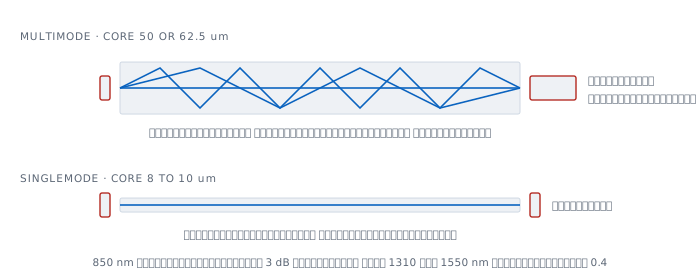
Fibre has no external noise or crosstalk problem at all, because light is not produced by the electromagnetic fields of neighbouring equipment. It has its own new set instead.
Multimode has a wide core, 50 or 62.5 microns, wide enough that light can take several paths. A ray that bounces off the walls many times travels further than one going straight, so it arrives later. A sharp pulse therefore spreads by the time it arrives, and spreads more with distance, until adjacent pulses overlap enough to be indistinguishable.
Singlemode solves it by shrinking the core to 8 to 10 microns, small enough that only one path remains. The problem disappears entirely.
The loss differs sharply too.
  multimode    at  850 nm    ~3    dB/km
  singlemode   at 1310 nm    ~0.4  dB/km
3 dB means losing half, so at 850 nm half the light is gone in one kilometre.
Multimode is designated OM1 through OM5 and singlemode OS1 and OS2, and the choice is not about distance alone — multimode uses cheaper light sources that are easier to align, so it still pays over short runs.
Where it lies to you
"The link light is on, so the cable is fine." No. The link light says only that the PHY hears enough from the far end to declare a link. It says nothing about the error rate. A cable that damages one frame in a hundred still lights it beautifully.
"If auto-negotiation is giving trouble, just force the speed." This is the advice that creates the most duplex mismatches. Forcing one end leaves the other hearing nothing and guessing, and it always guesses half. If you force, force both ends.
"A cable either works or it does not." No. Cable degrades gradually, and degrades at high frequencies first. The normal symptom is working at low speed and failing at high speed, or passing small frames and failing large ones.
"Gigabit uses two pairs like fast Ethernet." It does not. Gigabit needs all four. A cable with one broken pair runs 100 happily and will not link at gigabit.
"With fibre, more light is better." No. The receiver has an upper limit too. Putting a long-reach module on a two-metre patch overloads it, and the symptom looks exactly like having too little light.
Worked examples from real work
Case 1 — slow only under load, but ping never fails
Ping never drops, but copying a large file is far slower than it should be.
How to read it. Look at the counters on both ends. The information is in the asymmetry, not in either side alone.
switchA# show interface Gi1/0/7 | include duplex|coll|CRC
  Full-duplex, 100Mb/s, media type is 10/100/1000BaseTX
     0 late collision, 0 deferred
     2841 input errors, 2841 CRC, 0 frame, 0 overrun
switchB# show interface Fa0/7 | include duplex|coll|CRC
Half-duplex, 100Mb/s
1174 late collision, 293 deferred
0 input errors, 0 CRC, 0 frame, 0 overrunOne end full, the other half, and the counter pattern matches the section above exactly — the half end sees late collisions, the full end sees CRC, and neither sees both.
A bad cable would give both ends comparable CRC counts. That asymmetry is what separates the two cases.
Not yet proved. We know the duplex settings disagree, but not who hard-set theirs or when. Read both port configurations before changing anything, and fix the cause rather than forcing the other end to match.
Case 2 — will not link at gigabit, but 100 works fine
The port supports gigabit, the far device supports gigabit, and the link comes up at 100.
How to read it. First confirm it negotiated down rather than being forced.
switch# show interface Gi1/0/22 status
  Port      Name    Status      Vlan  Duplex  Speed Type
  Gi1/0/22          connected   10    a-full  a-100 10/100/1000BaseTX
The a- prefix means negotiated, not hard-set, so both ends agreed that gigabit was not achievable.
Then ask the cable directly, with TDR.
switch# show cable-diagnostics tdr interface Gi1/0/22
  Pair  Length        Remote Pair  Status
  1-2   32 m +/- 4 m  Pair 3-6     Normal
  3-6   32 m +/- 4 m  Pair 1-2     Normal
  4-5    1 m +/- 4 m  N/A          Open
  7-8   32 m +/- 4 m  Pair 7-8     Normal
Pair 4-5 is open at about one metre, while the other three run the full 32.
Read together with the section on pairs and it resolves immediately — 100BASE-TX uses only pairs 1-2 and 3-6, both of which are good, so it works. 1000BASE-T needs all four, so it does not.
The one-metre figure also suggests the fault is near a plug or the wall outlet rather than mid-run.
Not yet proved. The length TDR reports is computed from the NVP the tester is configured with, not this cable's actual value, so it is an estimate — and the plus or minus four metres it prints says as much itself.
Case 3 — CRC errors that move with the cable, not the port
A port is accumulating CRC errors, and it is not yet known whether the fault is the port, the cable, or the far device.
How to read it. Run an experiment that isolates one variable at a time. Clear the counters, take a baseline, then change one thing.
switch# clear counters interface Gi1/0/15
switch# show interface Gi1/0/15 | include CRC
     0 input errors, 0 CRC, 0 frame, 0 overrun
Wait fifteen minutes and read again: 412 CRC. Then move the same cable to a different port, clear the counters, and wait another fifteen minutes.
If the errors follow, the fault is in the cable or the far device. If they do not, it is the original port.
Not yet proved. If the errors follow the cable, we still cannot separate the cable itself from the device on its far end. That needs one more experiment: change the cable while keeping the far device. One experiment eliminates one variable, not all of them.
Case 4 — a short fibre run that will not work
New module, new cable, three metres inside one rack, and errors constantly.
How to read it. Read the actual optical power from the module.
switch# show interface transceiver detail
                        Optical    Optical
                        Tx Power   Rx Power
  Port                  (dBm)      (dBm)
  Te1/1/1               -2.1       -1.8
Receiving -1.8 dBm, barely different from what was transmitted, because the cable is three metres long.
If this is a long-reach module, it is designed for light that has travelled ten kilometres before reaching the receiver, so the receiver expects a far weaker signal. Given the full strength it saturates, and reads wrongly.
The fix is an attenuator, or a short-reach module matched to the job.
Not yet proved. Open that module's datasheet and check its acceptable receive range before concluding. -1.8 dBm is not automatically too high; it is too high only if it exceeds the maximum the datasheet states.
References
Standards
- IEEE 802.3 owns everything on this page, each variant in its own clause — 10BASE-T, 100BASE-TX, 1000BASE-T, 1000BASE-X, 10GBASE-R
- IEEE 802.3bz-2016, approved 23 September 2016, added 2.5GBASE-T and 5GBASE-T by cutting 10GBASE-T's signalling rate to a quarter and a half
- IEEE 802.3 Clause 28 owns auto-negotiation — the FLP burst built on top of 10BASE-T's link-integrity pulse, its 33 pulse positions per burst, and the parallel detection fallback for partners that cannot negotiate
- TIA-568.2-D sets maximum insertion loss at every frequency for every cable category — a Cat 6A channel at 500 MHz may not exceed 39.1 dB
- IEEE 802.3 working group material on FEC and PAM4 encoding in 802.3bj
What is on the machine
ifconfig -m en5on macOS — thesupported medialist showing how many separate standards one port implementsinclude/uapi/linux/mii.hin the Linux kernel — the whole 16-bit base page, the gigabit bits living in the separate register0x09, and the bit positions that mean different things on copper and on 1000BASE-X
Cable, light and measurement
- The Fiber Optic Association — Fiber Optic Cable core sizes, wavelengths, loss per kilometre, and modal dispersion
- Fluke Networks — Propagation Delay and Measuring cable length using NVP where NVP comes from and how TDR turns time into distance
- Siemon — where the 100-metre budget comes from the 90 and 10 metre split, and why the distance was held constant
Related reading here
- Ethernet — the frame that rides on all of this, and the 64-byte minimum computed purely from travel time
- MAC address — what sits one layer up
- Spanning Tree — what had to be built because the frame has no age field